
An outline for a DMAIC/Six Sigma project related to energy savings and increased run-times from more efficient suction roll operations.
Almost every paper machine has at least one suction roll, and some have as many as five, plus spares. They are a critical path element in the operation of the machine, and improper operation can significantly impact power consumption, and decrease the operating interval between changes.
Description:
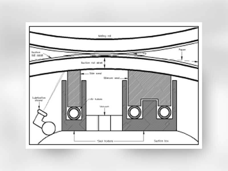
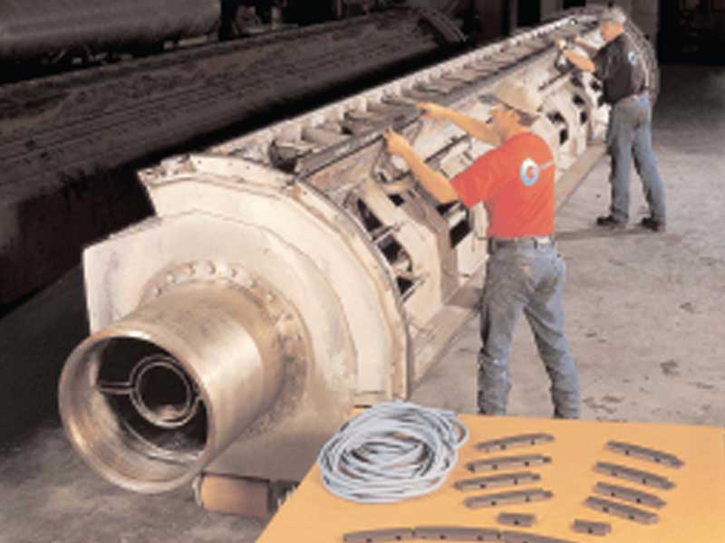
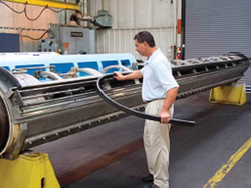
A typical seal assembly is shown in Figure 1. In most modern designs, the side and silencer seals rest upon air tubes that lie under the seals in a U-shaped holder. The end deckles can be either fixed or resting on springs. The exact configuration depends on the manufacturer of the suction roll and the position.
Everyone understands what the seal is supposed to do – keep the vacuum from leaking. However, very few understand how the suction roll seal assembly is designed to work and that is the source of much of the wasted power and shortened run times.
Wooden seals resting on springs were used in early suction rolls. Later rolls used seals of UHMW, asbestos, Micarta or Kevlar. The most common material today for modern high-speed machines is a rubber-graphite (RG) composite resting on a flexible tube instead of springs.
A common misconception is that the tube is there to “load” the seal into the shell, but the tubes are intended to be variable tension springs. The purpose of the springs in the original designs, and thus the tubes in more modern designs, is to let the seals or deckles depress away from the shell, not to lift the seals into the shell. If the seals and deckles can depress, then water can lubricate the seals and let them glide on the shell.
Water itself can seal the vacuum even if the seal is 0.5mm (0.020”) below the shell. Therefore the pressure in the tubes is designed to be very light, 0.3 Bar or less (< 5 psi) in most rolls.
Excess pressure in these tubes can turn the seal assembly into a brake. Nothing is visible from the outside of the roll to indicate any problems, but significant energy can be wasted, plus seal life and run-times decreased. Only by comparing drive loads under various tube pressures while maintaining vacuum does the scale of the problem become apparent.
In one test done by a major suction roll OEM, the difference in power between running a 5 meter suction roll at 1.0 Bar pressure in the tubes, versus 0.3 Bar, was found to be in excess of 100 amps! According to Fisher International, paper mills in the United States and Europe pay from USD 0.035 to USD 0.114 per kw-hr depending on the power source. 100 amps of wasted power can therefore cost between USD 25,000 and USD 65,000 per year on each roll.
Some suction rolls cannot reach full vacuum at 0.3 Bar tube pressure. There are several explanations. Rolls that have had shells bored or honed have a much bigger gap to close, for example. The problem is not unique to older rolls. Even in new suction rolls there are manufacturing tolerances on the bore diameter and on the fabricated suction box, yet the seal height that is supposed to close the gap between the two is typically the same for a given OEM.
The most economical way to operate suction rolls with low air tube pressure while maintaining full vacuum is to have the seals custom fit to the roll, often by adjusting their height. The procedure to do this consists of taking exact measurements of the suction box and the shell I/D, and calculating how tall the seals should be to assure full vacuum at the lowest possible air tube pressure. When properly done, the seals should just lightly touch the shell, or be up to 0.020” (0.5 mm) clear of the shell with no pressure in the tubes. Vacuum is often possible with no pressure in the tubes, especially with certain roll designs. Always use the lightest pressure possible.
Lubrication is essential for the sealing assembly to work. The lubricant is typically a combination of white water and fresh water. Lubrication should be provided through showers located just before the lead-in seal with nozzles directed to hit the shell just before the seal. Lubrication is also provided by white water trapped in the holes of the shell as it passes over the vacuum zone. In higher speed machines showers are installed inside the vacuum zone to lubricate intermediate seals between vacuum zones and the silencer seals. It is very common for showers to be in the wrong place, or pointed in the wrong direction, and this should be checked at maintenance intervals.
Most seal materials contain some form of lubricating agent as well, from graphite to PTFE to silicone oil. These agents help lubricate the seal during brief intervals of dry contact with the shell, but none has significantly changed the need for water as the primary lubricant.
The effects of lubrication can be dramatic when it comes to power consumption. In a US mill that had consistently short seal life in a suction couch position, lubrication showers were added, and their seal vendor custom fit the seals to the roll. They saw an immediate effect. Seal life extended beyond the one-year interval they sought, and the drive load on the couch roll dropped 125 amps from the reduced braking effect. Correspondingly the load on the wire turning roll was reduced by 100 amps.
Another recent innovation that impacts power is the advent of flexible rubber graphite (RG) seals. By 2014 it is now clear that flexible RG seals are lasting longer than the classic rigid RG that has dominated the world market since the 1980’s.
Classic RG seals are extremely hard (75 Shore D) and extremely brittle and easy to break in shipment and in handling, but typically run very well in most rolls. A wear pattern in the shape of a smile is typically observed, with more wear in the middle than on the ends.
The flexible RG seals were originally developed to help solve the breakage and shipment issues. It was only after they were observed wearing far less than the classic RG in the same conditions that the operational improvement was understood.
The binder in classic RG does not conduct heat very well. If heat is applied to the top of the material, a temperature gradient will exist between the top and bottom for some time as the heat slowly moves through it. The material tries to expand from applied heat, but this temperature gradient limits the expansion of the bottom relative to the top causing the material to bend upwards toward the source of the heat.
In a suction roll during start-up the top of the seal contacts the shell as everything expands, and this contact generates localized friction heat. The seal grows toward the heat, thus into the shell, favoring more contact, heat, wear, and the familiar smile shaped wear pattern emerges. After an hour of operation the roll and seal reach thermal equilibrium, lubrication finds the voids, and the classic RG runs on, but already very worn.
The new flexible RG is simply too limber to lift its own weight from thermal expansion. Placed side by side with similar heat applied to the surface of classic and flexible RG, the classic variety was observed to raise 5 mm (0.200”) from a flat surface, while the flexible laid still. This lack of “thermal bowing” at start-up by the flexible RG has significantly reduced the amount of contact the seal has with the shell, greatly extending the seal life. Lack of contact also means no drag load and less power consumption. All RG has a low coefficient of friction, but the best coefficient of friction is the near zero contact these flexible RG seals provide.
Measurement
To properly measure the effects of these changes, certain data will need to be gathered on all suction rolls within the company. The first step would be a list of every suction roll in each machine, plus spares, showing an identifying roll number, position in the machine, manufacturer, and size.
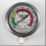
Next a base line of current operations needs to be established and two data points recorded for each roll. First, the current air tube pressure being used needs to be recorded in psi or kPa. Second, the current drive load needs to be recorded in amps. The air tube data can usually be read from a gauge on the tending side of the roll. The drive load data is sometimes displayed on a control panel, but in other cases a direct measurement may need to be made by qualified personnel. In addition, an energy cost per kilowatt hour will need to be known for each mill location.
Any data available regarding recent operating intervals of each roll should also be recorded along with any information regarding the purpose of the roll change. Some rolls are simply removed on a regular schedule, often annual, regardless of operating conditions, while others may be changed for some specific problem. This data can then be used to compare existing operations against benchmarking standards that are now available by suction roll position.
Analysis
From this data any rolls currently running with more than 3 to 5 psi of air tube pressure should be identified. Those rolls are the most likely candidates to be wasting energy in operation.
As each of these rolls is removed in the normal cycle, the measurements described above need to be taken and the seal heights adjusted as required to insure that these rolls can achieve full vacuum in the future with 5 psi or less in the air loading tubes. This service is available at no charge from some vendors when the rolls are apart either in the mill or in a roll repair facility. Use of flexible rubber graphite seals will further reduce contact with the shell, further enhancing the energy savings effect.
A new air load tube gauge can also be installed at this time with clear color coding showing the acceptable operating ranges for air load tubes. The use of these gauges will help deter “operator habit” of setting the pressure too high. Some training of maintenance and production personnel will be required.
As each of these rolls is returned to operation, the air tube pressure should be set at the minimum level required to maintain vacuum, even if that level is zero. The goal is to keep the tubes soft, operating as springs that let the seals stay lubricated.
Once each roll reaches equilibrium and operating temperature, usually within a few hours, new data needs to be recorded for the air tube pressure and drive load, using the same methods as in the original measurements. From this data, and the power cost per kilowatt/hour for a given location, the exact energy savings can be calculated as follows. For example:
Even a 10 amp savings in power to drive a suction roll adds up. Some rolls have saved over 100 amps.
With approximately 42 operating paper machines and an average of 2.5 suction rolls per machine operating at any one time, even a 10 amp savings on average could save over USD 350,000 of power. Savings in excess of USD 1,000,000 per year is well within reason.
In addition, if operating interval data is available and gathered, it could be compared against the following data gathered by Coldwater on operating intervals by grade of paper and machine position. If such data was not available then an initiative to gather it may be easier based on the existence of this benchmarking data. A separate analysis beyond the scope of this proposal would be required to determine the cost savings possible from extending run times into the top quartile of the industry.
Improvement & Control
Within one year, the majority of the suction rolls in the company could be documented, measured and improved to more efficient operation and a calculation made of the energy savings achieved. Within two years, virtually all suction rolls should have cycled through, and if priority is given to those running the highest air tube pressure in the initial analysis, then the vast majority of the energy to be saved should be completed and documented.
The use of the color coded gauges along with some basic training at the mill level should quickly identify any rolls operating outside of the acceptable range going forward. These rolls will then need further analysis and adjustments to the seals. All rolls should be checked for proper fit each time they cycle through an outside roll shop. The simplicity of the color coded gauges will make the efficiencies gained through this process relatively easy to maintain.
These steps will also improve seal life, and the operating intervals possible if the rolls are not changed on a scheduled basis. If all suction rolls in the company could operate in the top quartile, in excess of 650 days on average, then further savings would be achieved.
There is no capital investment required for this project. The data needed to verify the savings is readily available and can be gathered without great time or expense by existing mill personnel. The custom fitting service is available free of charge from Coldwater and from some roll repair facilities. Flexible rubber graphite seals are available from Coldwater and Metso and in the case of Coldwater costs the same as the original rigid rubber graphite.
(Source: Coldwater Group, Inc)