By Marcius H. de Oliveira,
Product Manager Canada, Capstone Technology
Abstract
Kraft bleaching is one of the most complex processes for control and optimization within the pulp and paper industry. The intricacy of this process is accentuated by the number of competing reactions at every bleaching stage, which is complicated further by mills using wood of varying quality. Each mill has a bespoke demand or parameter that needs to be realized, while focusing on the challenge of reducing chemical usage and inconsistencies in final brightness; and kraft bleaching mills already utilize several process solutions to meet this challenge, with kappa factor methodology, one of the more common.
Here we examine a control solution using Model Predictive Control (MPC) algorithms that is already in operation in a kraft bleach plant. To model the bleaching process, several process simulations were developed and software sensors relationships created to simulate the performance of online analyzers and inline sensors. We compare the kappa factor methodology and MPC and examine the key process indicators for optimization.
Introduction
Kraft pulp and paper mills are continually looking to optimize and modernize their processes, with many challenges in the fibreline, where the raw material (wood fiber) varies in several ways such as wood quality, wood age and seasonality. Process conditions, equipment age and other factors also impact the fibreline process.
The bleaching process within the fibreline area can address all these wood “changes” and process upset conditions as well as having responsibility for product quality delivery, product strength, minimal brightness variability and reduced chemical cost. Therefore, it is essential that reliable online measurements and effective process controls are developed.
The compensated brightness was one of the first bleaching process controls to be developed and was often applied to the first chlorinated stage (i.e.: D0). The compensated brightness was a strict calculation based on two inline sensors installed after the chemical addition, as described in the equation;
f = (Residual, Brightness)
These inline sensors were based on light source and a detector for reflected light, the first being a residual sensor (chlorine dioxide residual), and the second a brightness sensor.
Compensated brightness controls often overestimated dosages at the first stage and were not the ideal solution for a bleaching process. Additionally, these controls depended heavily on the reliability of the inline sensors.
Case Study – Kappa Factor Controls
Following the compensated brightness, the next generation of bleaching controls focused on kappa factor calculations and their impact on the delignification stages. To account for dissolved organic matter (namely black liquor carryover), other kappa factor relationships were also created, which were also known as compensated kappa factor controls. These controls were generally more robust than the compensated brightness and produced better results.
At Sappi’s Somerset Mill in Maine, United States, the kappa factor controls are based on inline sensors and online measurements of the inline brightness, inline residual and the kappa analyzer, which measures kappa and brightness at different locations. Kappa analyzer measurements are taken every 20-30 minutes and are essential to the kappa factor controls strategy. Single point kappa measurements have also been reported to be used for this type of control scheme.
To calculate the chemical dosage, these controls utilize a relationship of the kappa factor calculation and the incoming kappa to the bleach plant. It is important to note that the inline brightness and inline residual are also used in the overall control logic. This calculation is demonstrated by the equation;
         (% ClO2 ) × 2.63
KF = --------------------------
              Kappa#
Model Predictive Control
Based on a MPC platform, the MACS bleach controls were an alternative to the kappa factor controls.
MPC is a multivariable optimal control which can handle multiple constraints on manipulated and controlled variables by utilizing a set of linear dynamic models to represent the bleaching process and predict the effect of future control moves on the output variables. An optimization routine is also used to compute a set of future control moves while simultaneously ensuring that the process constraints are satisfied.
MPC’s are frequently based on the following variables:
- Controlled Variables (CVs) – These variables have setpoints or a high-low range that the controller will try to realize (Constraint Variables –CTs).
- Manipulated Variables (MVs) – These variables have new setpoints written to them by the controller to achieve the setpoints or respect the limits of the CVs.
- Feed Forward Variables (FFs) – These are variables which cause the controlled variables to change, but over which the user does not have direct control.
To take account of any irregularity in the process, it is important to use the correct process measurements. These measurements are used for feed forward disturbances and as feedback actions to compensate for unmeasured process disturbances or unwanted predictions.
Bleach Load Transmitter
The BTG Bleach Load Transmitter (BLT) has proven to be a robust inline measurement and the differential for the MACS bleach controls. The BLT measures the lignin present on the fiber and on the filtrate, giving the total bleach load (fiber kappa + filtrate kappa). The sensor measures the pulp stream at different wavelengths (blue, green, red and UV) by a group of LEDs. To achieve the LAB correlation with kappa these wavelengths can be combined. The main advantage of this sensor when positioned in the front end of the bleach plant is the ability to measure both the Kappa associated with the fiber wall and the organic matter produced as a liquid phase, or black liquor carryover. Measuring the volume of black liquor carryover entering the bleach plant is a significant challenge for controlling bleaching processes.
Figure 1 highlights the BLT sensitivity to black liquor carryover. The sensor identifies a process upset caused by the brownstock operator “flushing” the knotters, while the kappa analyzer misses that impact. This process upset resulted in lower E1 brightness, since MACS bleach controls were not online at that time.

MACS Bleach Controls
The primary objective at Somerset Mill was to deliver a control solution to improve the mills current kappa factor controls. The desired outcomes were defined as final brightness variability reduction and overall chemical savings.
Following a thorough audit of the Bleach Plant (Figure 2), a strategy was specified for the MACS bleach controls. The mill has one bleach line and processes two types of pulp species, with blended softwood (15%) and hardwood (85%) fibers, known as “co-pulp”, being the main pulp produced. The mill also processes softwood pulp species from 100% softwood fibers; however, as this accounts for less than 10% of the total pulp production, our study concentrates on the co-pulp results.
When defining the control scheme, it was decided to use the BLT measurement for the control scheme rather than use any kappa measurements coming from the bleach feed and extraction (E1) locations.
Consequently, a BLT factor software sensor was developed to account for any disturbance due to kappa variation and/or black liquor carryover disturbance. The BLT factor was also used to model and predict any desired targets at the end of E1 stage. The BLT factor is described below.
BLT factor = f (BLT, ClO2)

Using the BLT factor as one of the variables to control the E1 brightness and kappa was one of the advantages in the MACS bleach controls. Combining the BLT readings with the right MACS models resulted in excellent control performance for the D100 chlorine dioxide (ClO2).
Several control loop models were also created following development of the D100 ClO2 control models, as shown in Figure 3. It is important to note that some models have a feedforward characteristic, while others have a feedback characteristic. For instance, the controlled variable E1 brightness has feedforward models with the D0 and feedback models for D0 ClO2, E1 H2O2 and E1O2.

All models were created using MACS Model based on process simulations, where bump tests were planned and implemented. All models are linear with 1st order response, for example the D2 final brightness-controlled variable has two models, one feedback model (D2 ClO2 to D2 brightness), and one feed-forward model (E2 brightness to D2 brightness), as seen in Figure 4. The feedforward model is seen as a disturbance going into that stage, while the feedback model is a corrective model for the desired target chosen. Note that the large step response from the feedback model in Figure.4 is related to the dosage unit adopted in that mill.
It is also possible to vary the process gain for specific models in a nonlinear response environment. These variations can be customized using script codes that run inside the MPC controller software. It is not the intention of this article to mathematically describe tuning weights, optimization control equations, control horizon, etc., rather it is to describe an overall MPC application as an APC solution for bleach plants and its impact compared to another APC solution, such as the kappa factor.

brightness controlled variable, created using MACS Model
Only brightness samplers were present for the D1, E2 and D2 bleaching stages and no continuous brightness readings were available; therefore, a software sensor was required to predict brightness values in-between kappa analyzer samples. These continuous measurements were defined as “brightness estimators” and were created using a relationship between online brightness readings and their respective chemical dosage. For example, the D1 brightness estimator was defined as a relationship function between the D1 brightness from the kappa analyzer and the D1 ClO2, as seen in this equation;
D1Estimator = f (D1Brightness, D1 ClO2)
The bleach plant production rate was used to account for any fluctuation in the bleaching stages retention time. The rate was incorporated inside the MACS bleach as a variable input and used for varying the model’s delay for all control loops. This delay variation is important for optimum controls performance to ensure the correct delay time for the closed loop steady state predictions.
An additional benefit of the MACS bleach is its flexibility to be customized to any DCS platform. The requirements for a new MACS bleach installation would ordinarily be the OPC communication to DCS and a virtual server machine where the MACS Bleach software can be housed. The operator control interface at Somerset Mill has two main sections, the MV and CV sections. The operators can interact with the controls by adjusting chemical dosage MV Limits and CV target limits at each stage. It is important to mention that MACS Bleach will run an optimizer between MVs to reduce chemical consumption while maintaining target limits.
Results
When compared to the kappa factor controls, MACS bleach achieved positive results. Based on BLT readings, MACS bleach controls were able to respond quicker to disturbances entering the bleach plant. In addition, the controls model predictions allowed for better control optimization, which produced chemical dosages that were well balanced between stages, preventing any saturation event and resulting in higher chemical savings.
The E1 and E2 pHs control loops in MACS bleach also achieved positive results compared to the regular DCS pH control. The pH standard deviation is shown in Table 1, where a significant improvement is observed for MACS bleach controls versus DCS pH controls. The manipulated variables for E1 and E2 pH loops are the inlet pHs, while the controlled variables are the outlet pHs (Tower Extracted pHs). It is worth noting that the Inlet pH meters at the mill can be troublesome at times and should be checked and regularly maintained to ensure optimum control response.
Table 1. E1 and E2 Outlet/Extracted pHs
| MACS bleach | DCS control | |
| Comparison Period | 5 months | 5 months |
| E1 Outlet/Extracted pH | 9.70 | 9.69 |
| E1 pH STDEV | 0.17 | 0.38 |
| E2 Outlet/Extracted pH | 9.93 | 9.79 |
| E2 pH STDEV | 0.36 | 0.55 |
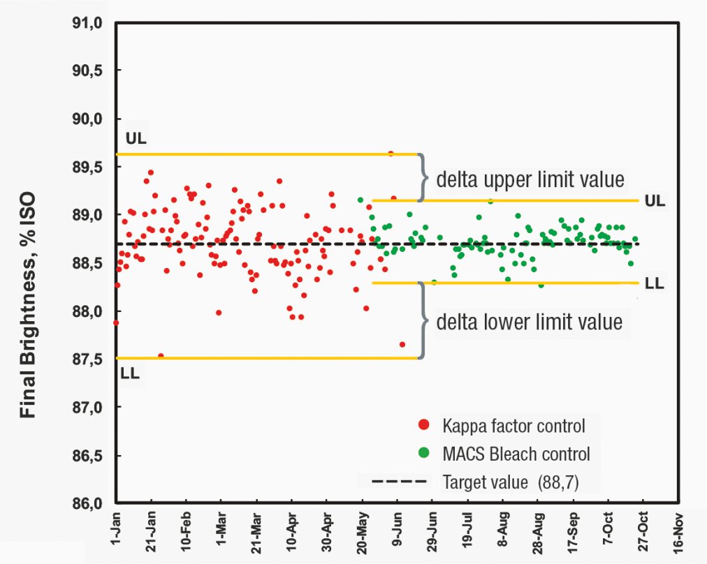
The final brightness standard deviation is one of the main parameters to assess the performance of any advance control solution in the bleaching process. At Somerset Mill, the final brightness standard deviation was evaluated between periods when the kappa factor controls were online against periods when the MACS bleach controls were online. Figure 5 denotes a 10-month period for co-pulp production, where a daily final brightness is shown.
The benefit shown in Figure 4 is highlighted below in Table 2. The final brightness standard deviation was 0.39 for MACS bleach controls and 0.80 for the kappa factor controls. This considerable reduction in final brightness variability permits the mill to apply a brightness target shift to achieve additional chemical savings.

KF controls and MACS bleach controls
Table 2: Final brightness standard deviation comparison, MACS Bleach and KF Controls
| MACS Bleach | KF Controls | |
| Comparison Period | 5 months | 5 months |
| Final Brightness AVG, % ISO | 88.7 | 88.7 |
| Standard Deviation | 0.39 | 0.80 |
Although the final brightness variability highlights the control performance, the main benchmark to indicate how well optimized any controls solution can be is the total chemical usage in the bleach plant. It is also the main parameter kraft mills use to define how successful a bleaching control solution can be, and the majority of pulp mills will base approval for implementing a specific control solution on predicted chemical savings.
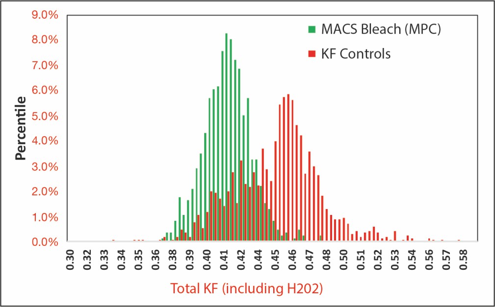
During a 10-month period, the daily total kappa factor was calculated for the bleach plant. This was chosen in order to normalize the total chemical dosage to kappa #. This calculation also included the peroxide dosage from E1 and E2 stages.

KF controls and MACS bleach controls.
The MACS bleach controls delivered an average of 0.413 total kappa factor with the KF controls delivering 0.446. This resulted in a 7.4% chemical saving for the MACS bleach controls compared to the KF controls, as highlighted in Figure 6 and Table 3.
Table 3. Chemical savings comparison, MACS bleach and KF controls
| MACS bleach | KF controls | |
| Comparison Period | 5 months | 5 months |
| Total Kappa Factor AVG | 0.413 | 0.446 |
| Chemical Savings | 7.4% | 0.0% |
Conclusions
Introducing the MACS bleach strategy at the bleach plant has been shown to be more advantageous than the regular kappa factor controls strategy. MACS bleach combined with BLT sensor has proved to be the correct route to take when improving and optimizing kraft bleach plants. By employing the correct strategy and control concept, MACS bleach and BLT readings look destined to be the future for advance controls in bleaching processes.
Acknowledgements
The authors like to thank Dylan Gustafson, Kristinn Kristinsson, Guy Normandeau, Dan Smith and Matt Janowicz for their valuable contributions. They also like to thank all mill team members involved in this project (Operations, E&I, LAB, etc). Without their support and engagement, none of this would have been possible.
References
- J. Williams, M. Williamson, Chapter 5: Sensors and Process Control. Pulp Bleaching Principles and Practice, TappiPress, 1996.
- Mathur A., Andersson N.,Damlin S. Proven alternatives to multi-point kappa analyzers for enhanced pulp mill process control.
- Andersson, N., et al., A new sensor and a novel control concept for optimized fiber line operation. TAPPI Journal, 2014. 13(10): p.39-45.


